
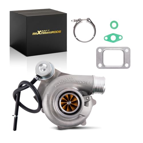
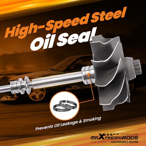
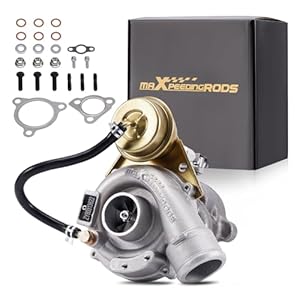
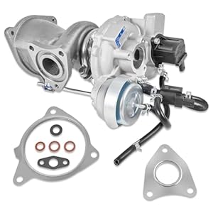
maXpeedingrods T25 Dual Ceramic Ball-Bearing Turbocharger for Custom 1.4L–3.0L Builds
Build a serious custom forced-induction system around this maXpeedingrods Sport SD Series turbocharger. Designed for 1.4L to 3.0L engines, it combines a T25 turbine inlet, dual ceramic ball-bearing center section, billet compressor wheel and oil-plus-water cooling.
The manufacturer advertises a 350–660 horsepower operating range, but this is a universal performance turbocharger—not a direct-fit replacement for every Honda Accord, Honda Civic or Ford F-150 listed in the marketing copy.
Installation requires a compatible manifold, downpipe, oil and coolant plumbing, intercooler system, fuel upgrades and professional ECU calibration.
Universal Engine Compatibility
The turbocharger is marketed for custom builds using:
- 1.4L to 3.0L engines
- Gasoline performance applications
- T25-flange exhaust manifolds
- Custom V-band downpipes
- Oil- and water-cooled turbo plumbing
- Target outputs between 350 and 660 horsepower
Engine displacement alone does not establish compatibility. Turbo selection also depends on airflow, pressure ratio, engine speed, volumetric efficiency, fuel type and desired response. Garrett’s turbo-selection guidance similarly treats displacement and target horsepower as starting points—not an automatic fitment chart.
$630.00
Advertised Vehicle Applications
The seller lists these broad project categories:
Honda
- Accord: 1976–1985 and 1995–2025
- Civic: 1975–2025
Ford
- F-150: 2015–2025
These year ranges do not represent bolt-on fitment. They include dozens of engines, chassis generations and factory induction systems.
A turbocharger cannot directly fit every Civic built since 1975 unless its mounting system consists primarily of imagination.
Honda Accord and Civic Fitment
Honda installation requires a manifold designed for the exact engine and a T25 turbo flange. Depending on the application, that could involve a D-series, B-series, K-series, L-series or another engine entirely.
A complete Honda installation generally requires:
- Engine-specific T25 turbo manifold
- Fabricated downpipe
- External wastegate or compatible internal-wastegate arrangement
- Intercooler and charge piping
- Blow-off or bypass valve
- Oil-feed and oil-return plumbing
- Coolant lines
- Larger fuel injectors
- Higher-capacity fuel pump
- ECU tuning
- Wideband oxygen sensor
- Upgraded clutch or transmission components
- Heat shielding
Older naturally aspirated Hondas also require an oil-return fitting added to the oil pan.
Ford F-150 Fitment Warning
This turbocharger is not a direct replacement for any 2015–2025 F-150 factory turbo.
The F-150 was offered with several engines, including naturally aspirated V6 and V8 options plus factory twin-turbo EcoBoost engines. Ford lists the 2025 F-150 with 2.7L EcoBoost, 3.5L EcoBoost and 5.0L V8 choices. Ford.com
Using this turbo on an F-150 would require a fully custom system. On an EcoBoost engine, it would involve redesigning a twin-turbo layout around a single universal turbo or constructing another specialized arrangement.
The advertised 1.4L–3.0L displacement range also excludes the 3.5L and 5.0L F-150 engines. Therefore, “2015–2025 F-150 compatible” should not be published as ordinary vehicle fitment.
Turbocharger Specifications
| Specification | Details |
|---|---|
| Advertised horsepower range | 350–660 hp |
| Suggested displacement | 1.4L–3.0L |
| Bearing system | Dual ceramic ball bearing |
| Cooling | Oil and water |
| Compressor wheel | Machined billet aluminum |
| Compressor inducer | 54.4 mm |
| Compressor exducer | 67.4 mm |
| Compressor trim | 65 |
| Compressor housing A/R | 0.70 |
| Turbine inducer | 53.9 mm |
| Turbine exducer | 49.55 mm |
| Turbine trim | 84 |
| Turbine housing A/R | 0.49 |
| Turbine inlet | T25 flange |
| Turbine outlet | 90 mm OD V-band |
| Outlet centering ring | 81 mm |
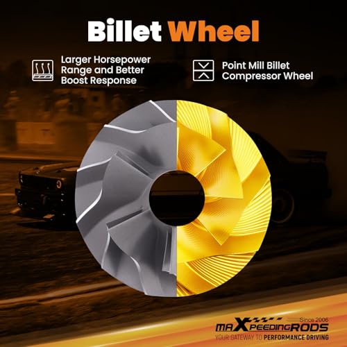
Billet Compressor Wheel
The fully machined billet-aluminum compressor wheel is designed for strength, low rotating mass and efficient airflow. Compared with a heavier wheel, reduced rotating mass may improve response when the rest of the turbo system is properly matched.
Actual spool behavior depends on:
- Engine displacement
- Compression ratio
- Exhaust-manifold design
- Turbine housing size
- Camshaft specifications
- Exhaust backpressure
- Boost target
- Gear ratios and vehicle weight
A billet wheel cannot compensate for a poorly matched turbo. It simply spins very nicely while reminding you that compressor maps exist.
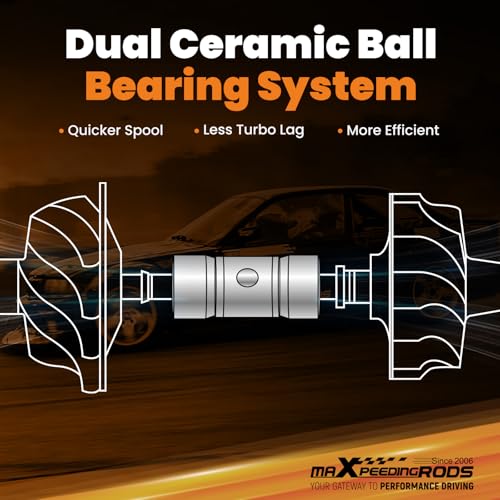
Dual Ceramic Ball-Bearing Center Section
The dual ball-bearing center housing reduces friction compared with a basic journal-bearing design. Potential advantages include:
- Faster transient response
- Reduced shaft friction
- Improved rotor stability
- Lower oil-flow requirements
- Better response between gear changes
- Increased durability when properly lubricated
Ball-bearing turbos generally require controlled oil pressure. Garrett recommends an oil restrictor for ball-bearing turbochargers and stresses verifying pressure at the turbo inlet. Garrett Motion
Use the pressure and restrictor specifications supplied by maXpeedingrods for this exact unit. Do not automatically copy another manufacturer’s restrictor size.
Oil and Water Cooling
This turbo uses engine oil for bearing lubrication and coolant circulation to control center-housing temperature.
Proper water-line routing helps reduce heat soak and oil coking after shutdown. Garrett explains that water cooling protects the center housing during operation and continues removing heat through thermal siphoning after the engine stops. Garrett Motion
Installation requires:
- Correct oil-feed pressure
- Properly sized oil restrictor
- Unrestricted gravity oil drain
- Heat-resistant oil lines
- Coolant feed and return lines
- Correct line routing away from exhaust heat
- Turbo priming before initial startup
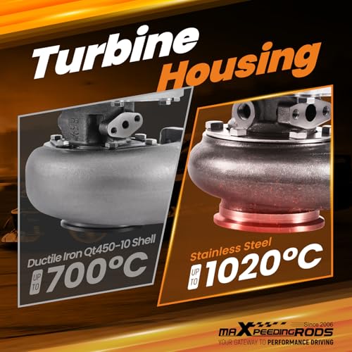
High-Temperature Turbine Construction
The stainless-steel turbine housing is advertised to withstand temperatures up to 1,868°F, while the turbine wheel is rated for operation up to approximately 1,832°F.
Those figures describe material-temperature capability, not a recommended continuous exhaust-gas temperature. Actual safe operating limits depend on fuel mixture, ignition timing, turbine pressure and sensor location.
Sustained excessive exhaust temperature can still damage the turbocharger, exhaust valves, manifold and catalytic converter.
Understanding the 660-Horsepower Claim
The advertised 660-horsepower figure represents a potential airflow ceiling under suitable conditions. It does not mean every engine will produce 660 horsepower after installation.
Garrett notes that published maximum turbo power is generally based on compressor choke flow and represents potential flywheel output—not guaranteed wheel horsepower. Garrett Motion
Actual output depends on:
- Engine airflow
- Boost pressure
- Fuel type
- Fuel-system capacity
- Intercooler efficiency
- Cylinder-head flow
- Exhaust restriction
- ECU calibration
- Drivetrain losses
- Engine mechanical strength
A stock 1.5L Civic engine and a built 3.0L six-cylinder will not produce the same result merely because they share a turbo.
Additional Components Required
This turbocharger alone is not a complete conversion kit. Most installations require:
- T25 exhaust manifold
- Wastegate and dump tube
- V-band downpipe
- Intercooler
- Charge piping
- Blow-off valve
- Intake and air filter
- Oil-feed kit
- Oil-return kit
- Coolant lines
- Fuel injectors
- Fuel pump
- Boost-control solenoid
- Wideband oxygen sensor
- ECU calibration
- Heat shields
- Appropriate engine and drivetrain upgrades
Check Engine Health Before Adding Boost
Before installation, perform:
- Compression testing
- Cylinder leak-down testing
- Oil-pressure testing
- Cooling-system pressure testing
- Fuel-pressure testing
- Crankcase-ventilation inspection
- Ignition-system inspection
- Timing-system inspection
Review Pro Street’s guide to checking engine health before adding boost before starting the conversion.
Boost does not repair a weak engine. It simply helps locate the weakest component with remarkable efficiency.
Installation and First Startup
Professional fabrication and tuning are strongly recommended.
Before starting the engine:
- Verify the turbo rotates freely.
- Flush all fabricated lines and pipes.
- Install the correct oil restrictor.
- Confirm unrestricted oil drainage.
- Connect and bleed the coolant lines.
- Prime the center housing with clean engine oil.
- Crank the engine without starting until oil pressure develops.
- Pressure-test the intake system.
- Verify wastegate plumbing and spring pressure.
- Begin tuning at the lowest practical boost setting.
- Monitor oil pressure, air/fuel ratio and boost.
- Inspect for leaks after the first heat cycle.
Specification: maXpeedingrods T25 Dual Ceramic Ball-Bearing Turbocharger for Custom 1.4L–3.0L Builds
|
User Reviews
Be the first to review “maXpeedingrods T25 Dual Ceramic Ball-Bearing Turbocharger for Custom 1.4L–3.0L Builds”
You must be logged in to post a review.




There are no reviews yet.